
Whole Home Humidifier Electrical Wiring: A Minnesota Code Guide
Key Takeaways
- Whole home humidifier electrical wiring splits into two separate circuits: a 120V tap for the transformer and a Class 2 18 AWG 2-conductor low-voltage run for the 24V control signal.
- Minnesota requires an electrical permit any time new wiring is added, and that includes humidifier installations.
- Most Twin Cities municipalities are local Authorities Having Jurisdiction. File the permit with your city, not with state DLI.
- Minnesota is mid-transition to the 2026 NEC. The code that applies is determined by the permit filing date, not the date the work is done.
- Fan-powered humidifiers require an additional G or W terminal connection to the furnace control board. Bypass units do not.
- Modern humidistats with outdoor temperature compensation add a third wire run that most DIY guides skip entirely.
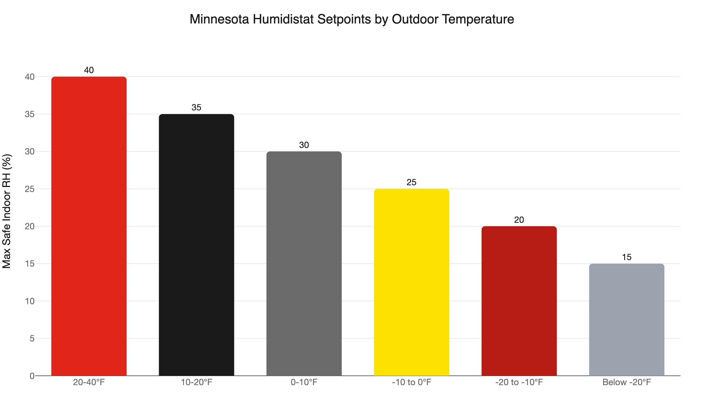
- Set your humidistat by outdoor temperature. At minus 20°F or colder, the maximum safe indoor RH is 15%.
- No Minnesota rebate currently covers whole-home humidifiers.
- Unpermitted humidifier wiring can void homeowner’s insurance and create a material disclosure issue at closing.
Does Whole Home Humidifier Electrical Wiring Require a Permit in Minnesota?
Yes. Any installation that adds new wiring - and nearly all whole-home humidifier installs do - requires an electrical permit under Minnesota law. Skipping the permit can void your homeowner’s insurance and flag the work as a material defect during a home sale.
Minnesota’s electrical code is Chapter 1315 of the State Building Code, which adopts the National Electrical Code (NEC, NFPA 70) as the standard for all residential electrical work. That adoption is not optional guidance. It is the law.
One detail that trips up Twin Cities homeowners: the permit filing goes to your city, not to the state. About 66 Minnesota municipalities operate as local Authorities Having Jurisdiction, meaning they run their own electrical inspections and issue their own permits. Minneapolis, St. Paul, Bloomington, Woodbury, Plymouth, Maple Grove, and most other Twin Cities suburbs are on that list. If you file with the Minnesota Department of Labor and Industry (DLI) when your city is the local AHJ, the permit lands in the wrong system. The inspection may never get triggered.
If you are not sure whether your city is a local AHJ, call your city’s building department before filing anything. That one phone call saves you from starting over.
The 2026 NEC transition. Minnesota is in the middle of a code changeover right now. Permits filed before August 17, 2026 must comply with the 2023 NEC. Permits filed on or after August 17, 2026 must comply with the 2026 NEC. For most humidifier wiring, the practical difference is small. But the applicable code is determined by when the permit is filed, not when the work happens. If you pull the permit today and the inspection is next month, the 2026 NEC governs the job.
Owner-occupant DIY. Minnesota allows homeowners to do electrical work only on their own owner-occupied single-family homestead, with a permit, an inspection, and the homeowner doing the work personally. Rental properties are off the table entirely. Hiring an unlicensed handyman is a code violation regardless of who owns the home. The permit requirement exists whether you do the work yourself or hire a licensed contractor. The only question is who can legally hold the permit.
What Does Whole Home Humidifier Electrical Wiring Actually Involve?
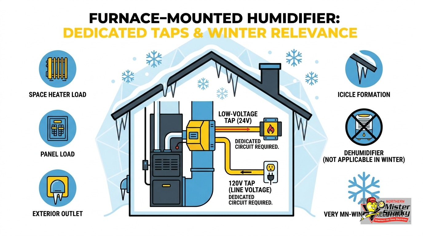
Two separate circuits. A 120V tap powers the transformer that steps household voltage down to 24V AC. An 18-2 low-voltage run carries the 24V control signal between the humidistat, the furnace control board, and the solenoid valve. These circuits are governed by different NEC sections and are not interchangeable in method or material.
Most DIY wiring guides describe the process procedurally: connect this terminal, run that wire. The code sees it as two distinct systems with different rules for wire gauge, conduit, and separation from other wiring. Understanding the distinction prevents the most expensive mistakes.
The 120V side. The transformer converts 120V house current to 24V AC for the control circuit. The 120V connection must go into a grounded metal junction box with a proper 7/8-inch knockout. It cannot connect directly to the furnace blower motor circuit. The transformer VA rating - 10 VA for most bypass humidifiers, 15 VA for larger flow-through units - determines the load requirements on the 120V side.
The 24V Class 2 side. From the transformer secondary, 18 AWG 2-conductor wire runs to the humidistat and to the furnace control board. Most modern furnaces have a dedicated HUM terminal and a separate NEUTRAL terminal for the 110V return leg. The NEUTRAL is not the 24V common. Swapping them damages the furnace control board - a repair that typically runs several hundred dollars, well above what a correct installation would have cost. The voltage at the control board must stay between 22 VAC and 30 VAC for the humidifier call to function reliably.
Which NEC Article Governs Each Circuit?
The 120V transformer side is governed by standard NEC branch circuit and appliance wiring rules under Chapters 1 through 4. The 18-2 low-voltage control run is Class 2 wiring under NEC Article 725. These are separate regulatory frameworks with different requirements for wire gauge, conduit, and clearances from line-voltage wiring.
This distinction is exactly what most DIY wiring guides miss. They describe the wiring steps without explaining which code layer governs each one. So readers follow the procedure without knowing why the rules are different for each wire - or what crossing those rules actually means for the inspection.
Class 2 wiring can be run without conduit in most residential applications. It uses smaller gauge wire and has different separation requirements from standard 120V branch circuit wiring. The NEC created this separate classification intentionally: the voltage and current are low enough that the failure risk profile is different from a standard branch circuit. But that latitude comes with its own rules. You cannot substitute a different wire type and expect it to meet code just because the voltage is low.
If your electrician or inspector mentions “Class 2” or “Article 725,” they are talking about the low-voltage control run. If they reference junction box requirements, grounding, or breaker sizing, they are on the 120V side. Both conversations belong on the same permit.
Is Fan-Powered Humidifier Wiring Different From Bypass?
Yes, meaningfully so. Fan-powered humidifiers require an additional G (fan call) or W (heat call) low-voltage connection to the furnace control board. Bypass humidifiers do not need this wire because they use the furnace blower’s existing airflow rather than their own motor.
This extra wire is the detail every DIY wiring diagram leaves out for fan-powered units.
A bypass humidifier mounts between the supply and return plenums. When the furnace blower runs, the pressure difference between the two sides pushes air through the evaporator pad. The humidistat signal opens the solenoid valve; the furnace does all the airflow work. The wiring is relatively straightforward: 24V solenoid, HUM terminal connection, humidistat.
A fan-powered humidifier has its own small blower motor. It can humidify even when the furnace is not actively running a heat cycle, which makes it more effective during mild weather when the furnace does not run frequently. But that motor needs a signal to tell it when to operate. The G or W connection to the furnace control board provides that signal.
Never connect both G and W to the humidifier terminal simultaneously. The installation manual for your specific unit specifies which terminal to use. Wiring it wrong does not immediately damage the humidifier, but it causes the unit to run at the wrong times and produces erratic humidity control that is difficult to diagnose.
Transformer sizing by unit class. Bypass units in the HE100/HE200 class typically use a 10 VA transformer. Larger flow-through units in the HE150/HE250 class typically use a 15 VA transformer. The 120V side of the transformer connects to the furnace junction box, not to the blower motor circuit. If the transformer is undersized for the unit, the solenoid will not open reliably and humidity levels will fall short of the setpoint with no obvious fault code.
For context on why appliance circuits require their own dedicated capacity, see our post on dedicated circuits for appliances.
What About the Outdoor Temperature Sensor Wire?
Modern humidistats with outdoor temperature compensation add a third wire: a 2-conductor low-voltage run from the indoor humidistat to an outdoor sensor. No DIY wiring guide covers this, but in Minnesota it is the feature that makes a whole-home humidifier actually safe over the long term.
Without outdoor temperature compensation, you set a fixed RH target and must remember to lower it manually every time a cold front arrives. In the Twin Cities, that means checking and adjusting the setting multiple times throughout winter. Miss an adjustment during a polar vortex week and you can drive condensation into the wall cavity without knowing it until you open the wall.
An outdoor-compensating humidistat adjusts the setpoint automatically as temperatures drop. The outdoor sensor wire is typically 18 AWG 2-conductor, run from the humidistat location to a protected spot on the exterior wall - similar to the low-voltage wire used for a smart thermostat’s outdoor sensor. It carries a low-level signal, not 120V, and must be separated from line-voltage wiring where it shares a wall cavity or conduit chase.
If your installation plan includes an outdoor-compensating humidistat, add that third wire run to the permit scope when you file. It is not a separate permit - it is part of the same job. But the inspector needs to know it is part of the plan.
How Should You Set the Humidistat for a Minnesota Winter?
Drop the setpoint as the outdoor temperature drops. At minus 20°F or colder, the safe maximum is 15% indoor RH. Set it higher and you push moisture through the insulation to condense on cold sheathing - which turns a well-executed electrical installation into a concealed moisture damage problem.
This is the concern that Minnesota’s Center for Energy and Environment (CEE) raises when they recommend individual portable units over whole-home systems. Their argument is not that whole-home humidifiers are bad. It is that a forgotten setpoint can rapidly over-humidify a house, causing moisture damage inside walls that no one sees until the drywall comes down. The right response to that concern is not to skip the whole-home unit. It is to set it correctly for conditions.
The chart below shows the safe indoor RH ceiling at each outdoor temperature range.
[CHART: mn-humidistat-setpoints]
These numbers follow condensation physics, not comfort preferences. When outdoor air is very cold, the dew point inside the wall cavity drops. If indoor RH exceeds the condensation point at the sheathing temperature, moisture migrates through the insulation and condenses on the wood or OSB behind the drywall. Mold, rot, and structural damage follow - none of which you installed a humidifier to cause.
If you have an outdoor-compensating humidistat, these adjustments happen automatically. If you have a manual humidistat, bookmark this table. Check it whenever the forecast drops below 10°F, and again when it drops below zero. The Twin Cities regularly sees minus 20°F in January and February. The setpoint that worked fine in November is wrong by February.
Can You DIY Whole Home Humidifier Electrical Wiring in Minnesota?
Owner-occupants of a single-family homestead may do the work themselves with a permit and inspection, doing the work personally. But the two-circuit structure, the correct AHJ for permit filing, and the seasonal humidistat calibration are all places where getting it wrong costs significantly more than a licensed electrician would have charged.
Unpermitted electrical work can void homeowner’s insurance and surface during a home sale as a material defect that requires disclosure. In Minnesota’s real estate market, that is a renegotiation or a deal that collapses.
The most common wiring failures we see in unpermitted humidifier installations:
- The 120V transformer wired directly into the blower circuit instead of a dedicated junction box
- The furnace NEUTRAL terminal and the 24V common swapped, burning out the control board
- Wire gauge too small for the transformer VA rating
- A fixed humidistat setpoint left at 40-45% through a January cold snap, driving condensation into the walls
Every one of these is detectable at inspection. Every one costs more to correct than a correct installation would have cost in the first place.
The installation may also surface upstream problems. If the furnace junction box is already crowded, or if the panel is short on available capacity, the humidifier install reveals a situation that needs its own answer. See our guide to signs you need an electrical panel upgrade if the capacity question comes up during the walk-through. And if the furnace wiring more broadly needs attention, our post on furnace electrical wiring and disconnect switches covers that territory.
What if My Furnace Already Has a HUM Terminal?
The 24V control side is simpler. The furnace board handles switching, so you do not need a separate relay or external control circuit. But you still need the 120V transformer connection in a proper grounded junction box, and you still need a permit for any new wiring.
Modern furnaces from the last 15 to 20 years typically have a dedicated HUM terminal that activates when both a heat call and a humidifier call are present simultaneously. The humidistat signal goes to the HUM terminal, and the board controls when the solenoid opens. This simplifies the wiring diagram because the relay function is built into the furnace.
A HUM terminal does not eliminate:
- The 120V transformer properly mounted to a grounded metal junction box with the correct knockout
- 18-2 wire from the transformer secondary to the humidistat and to the HUM terminal
- Correct identification of the NEUTRAL vs. the 24V common on the board
- A permit and an inspection by the correct AHJ
If your furnace is older and does not have a HUM terminal, the control circuit is more involved and almost always requires a licensed electrician. Older furnace control boards vary significantly in how they handle external accessory loads. Getting this wrong does not just affect the humidifier - it can affect how the furnace itself calls for heat.
Does a Whole Home Humidifier Qualify for a Minnesota Rebate?
No. No current Minnesota rebate covers whole-home humidifiers. Xcel Energy’s 2024-2026 program covers gas furnaces, heat pumps, central AC, smart thermostats, insulation, and water heaters. Humidifiers are not on the list.
Minnesota’s IRA-funded HEAR and HOMES programs have no confirmed launch date as of August 2026, and humidifiers are not included in either program regardless. The programs target measurable energy reduction; a humidifier does not produce a calculable energy savings figure that a rebate program can validate.
The value of a whole-home humidifier is comfort, protection for hardwood floors and cabinetry, and reduced static in an environment that otherwise drops to single-digit RH in January. Those are real benefits. They are just not tied to a rebate. Go in with accurate expectations and the installation is still a sound investment for most Twin Cities homes.
Let Northern Mister Sparky Handle the Wiring
Whole home humidifier electrical wiring is one of those jobs that looks simple until the permit question, the two-circuit structure, and the Minnesota-specific humidistat setup all arrive at once. Our team handles all of it. We know which Twin Cities cities run their own AHJ inspections. We know how to route the 120V tap correctly and how to set a humidistat so you are actually protecting your home instead of quietly damaging it from the inside.
We are locally owned and operated, and we back every job with the UWIN(R) 100% satisfaction guarantee. As America’s On-Time Electrician(R), we show up when we say we will - no malarky, no excuses.
If you are planning a furnace-mounted humidifier this fall or winter, or if you have one that was installed without a permit, call us at 763-200-5956 or book online. We will scope the full electrical picture, pull the permit with the right authority, and get the wiring done right the first time. If the project surfaces a panel capacity question, we handle that too - all under one roof.
Frequently Asked Questions
Does a whole home humidifier installation require an electrical permit in Minnesota? +
What wire is used for the humidifier low-voltage control circuit? +
Can a Minnesota homeowner do their own whole home humidifier electrical wiring? +
Need an electrician now?