
Well Pump Electrical Requirements for Minnesota Homeowners
Key Takeaways
- Minnesota adopted the 2026 NEC on August 17, 2026. All permits filed on or after that date must comply with the updated code.
- All well pump electrical work in Minnesota requires a permit and a licensed electrical contractor under Minn. Stat. 326B.32.
- Conductors must be sized at 125% of motor full-load current per NEC 430.22, not the nameplate. For a 1 HP, 230V pump, that means 10 AWG copper at minimum.
- Minnesota’s frost line is approximately 42 inches in the Twin Cities metro. The NEC’s 24-inch burial minimum is not adequate here. Inspectors expect deeper burial and rigid conduit risers.
- Voltage drop controls wire sizing on any run over 200 feet. Outer-ring suburbs often need wire one to two gauges above the NEC ampacity minimum.
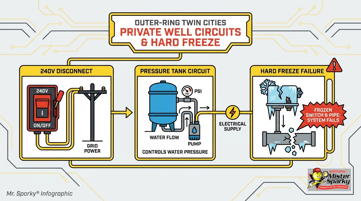
- Cold weather attacks well pump circuits in specific, predictable ways: pressure switch sensing port icing, capacitor failure below 0°F, short-cycling from a waterlogged pressure tank, and frost heave cracking conduit risers.
What Are the Well Pump Electrical Requirements in Minnesota?
Quick answer: Minnesota’s well pump electrical requirements follow NEC Article 430 for motor circuits, NEC 300.5 for underground wiring, and NEC 250.112(M) for bonding. Minnesota adopted the 2026 NEC on August 17, 2026. All permits filed on or after that date must comply. Every installation requires a licensed contractor and a permit.
If you live in Stillwater, Shakopee, Rogers, or another outer-ring Twin Cities suburb, your home may be on a private well. That well’s submersible pump is a motor load. Motor loads have specific code requirements for conductors, overcurrent protection, disconnects, grounding, and underground installation. Miss one, and you face shortened pump life, a shock hazard, or a failed inspection.
Minnesota adopted its electrical code under Minn. Stat. 326B.32, codified in Chapter 1315 of the MN State Building Code. The 2026 NEC took effect on August 17, 2026. Permits filed before that date go under the 2023 NEC. Your county permit office confirms which version applies.
Washington, Scott, Wright, and Hennepin county permit offices all follow the state effective date. If you are not sure which version applies to your job, call the county before starting work.
The core motor circuit rules from NEC Article 430 are consistent across both editions. The 2026 version tightens underground conductor protection and bonding provisions. Both of those directly affect well pump circuits.
Why Does Your Well Pump Need Its Own Dedicated Circuit?
Quick answer: A submersible pump is a continuous motor load with a start-up inrush current five to seven times the running current. Sharing a circuit with other loads risks nuisance trips, voltage sag that stresses the motor, and undersized wiring. A dedicated circuit isolates the pump and keeps the ampacity compliant with NEC 430.22.
Motor loads are different from a toaster or a light fixture. They draw a steady running current in normal operation. At start-up, they spike hard. For a well pump, that spike is five to seven times the running current.
If the pressure tank bladder has failed and the pump is short-cycling, those spikes hit every few minutes. Sharing a circuit with kitchen appliances, shop equipment, or any other heavy load compounds the problem. Voltage sag from concurrent loads causes the motor to draw more current to maintain speed. More current means more heat in the winding insulation.
Winding insulation failure is the most common cause of premature submersible pump motor death. A dedicated circuit removes one of the biggest contributing factors.
It also simplifies troubleshooting. When water pressure drops, an electrician goes directly to that breaker, the pressure switch, and the control box. No untangling shared circuits first.
For a broader look at why dedicated circuits matter across different appliances, see our dedicated circuits guide.
Well Pump Electrical Requirements: Wire Size, Breaker, and Control Box
Conductor sizing and breaker sizing follow separate rules for motor circuits. This combination surprises most homeowners, but each rule has a specific job.
Conductor sizing under NEC 430.22: The wire must be rated at 125% of the motor’s full-load current (FLC) from NEC Table 430.248, not the nameplate amperage. For a 1 HP, 230V single-phase motor, the FLC is 10A. Minimum conductor ampacity is 12.5A. That lands on 10 AWG copper at minimum for a short run.
Breaker sizing under NEC 430.52: Inverse-time breakers can be oversized up to 250% of FLC to handle inrush. For a 1 HP pump with 10A FLC, the maximum overcurrent device is 25A, typically rounded to a 30A breaker. That is intentional. The breaker handles inrush without nuisance trips. The control box overload relay handles motor overload protection separately.
How the three layers work together: The conductor rating protects against sustained overload heat. The overload relay in the control box trips on locked-rotor current before the motor burns. The oversized breaker handles start-up inrush. Each layer handles one failure mode.
Voltage drop changes everything on long runs: Outer-ring suburbs in Washington, Scott, and Wright counties regularly see 300 to 500 foot panel-to-wellhead runs. Many of those circuits use original 1970s and 1980s wiring. On a 300-foot, 240V, 10A run, 10 AWG wire drops more than the acceptable 3% threshold. You need 8 AWG. At 500 feet, 6 AWG is often required. A 10% voltage drop at the motor reduces efficiency approximately 20% and shortens winding life.
Our wire gauge and breaker size guide covers how these rules apply across other circuit types.
Where Does the Disconnect Switch Have to Go?
Quick answer: NEC 430.102 requires a disconnect within sight of the motor controller. For submersible pumps, the motor is 100 or more feet underground. A lockable disconnect at the wellhead pressure switch assembly qualifies as the code-equivalent location. A lockout clip on the panel breaker is the code-minimum alternative.
The within-sight requirement exists so that anyone working on the circuit can confirm power is off before touching anything. You cannot see the motor through 100 feet of 4-inch well casing. The code accepts the wellhead controller location as the functional equivalent.
What degrades wellhead disconnects in Minnesota is freeze-thaw cycling. Moisture works into weatherproof enclosures that are not fully sealed. Lug connections corrode over years. Corroded lugs create resistance. Resistance creates heat at the connection point. The result is an intermittent open circuit, arcing, or a melted terminal block.
Pre-2000 installs in Washington, Scott, and Wright counties frequently have original wellhead enclosures. If your disconnect is more than 20 years old and has never been inspected, lug corrosion is the most likely fault waiting for a cold January night to reveal itself.
Minnesota’s MDH well setback requirements also place the wellhead at least 10 feet from any energized overhead line. This affects where you can route the above-grade feed from the underground circuit to the wellhead enclosure.
How Does Voltage Drop Affect Your Well Pump?
Quick answer: A 10% voltage drop at the motor reduces efficiency approximately 20% and accelerates insulation failure. Runs over 200 feet require voltage drop calculations, not just code-minimum ampacity. Outer-ring suburbs routinely see 300 to 500 foot runs where the NEC minimum wire gauge is not adequate.
Voltage drop is invisible until the pump fails. The water comes out. The pressure seems normal. The system appears to work. But the motor is running hot every cycle, drawing higher current to compensate for low voltage.
Heat degrades winding insulation. Insulation failure is the most common cause of premature submersible motor death. A motor rated for 15 years may fail in eight if it runs at 90% voltage on most cycles.
The math is straightforward. Wire resistance causes voltage loss proportional to current and length. More length means more resistance. More resistance means more voltage lost before the motor terminals. Heavier wire has lower resistance and less drop.
Original well pump wiring from the 1970s and 1980s was sized to NEC ampacity minimum. No contractor calculated voltage drop at installation. Replacing the pump without running new, properly sized wire repeats the same shortened-lifespan problem on a new motor.
If your wellhead is more than 200 feet from the panel, voltage drop should be the first thing an electrician evaluates before recommending wire or permitting the work.
What Fails Electrically When Minnesota Wells Freeze?
Quick answer: Minnesota’s Zone 6a design lows of -20°F to -25°F create a specific electrical failure chain. Pressure switch sensing ports ice over and stop pump activation. Start capacitors fail below 0°F, producing locked-rotor current and a hum-then-trip symptom. Waterlogged pressure tanks cause short-cycling that fires repeated inrush spikes and destroys motor windings over a winter.
Most online guides treat well pump electrical specifications as a static installation checklist. In Minnesota, the more useful question is: what fails first when the temperature drops?
Pressure switch icing: The sensing port is a small orifice connecting water pressure to the switch diaphragm. In an unheated well house or an exposed mechanical room, that port ices over. When it does, the switch cannot sense pressure changes. You get no water, and the pump may not start despite the breaker being on. In some cases, the switch contacts weld from heat during a locked-rotor run condition. Continuous motor run burns windings fast.
Frozen sensing ports are the leading cause of pressure switch failure in cold climates. The fix is heat tape or a heated well house enclosure. Replacing the switch without addressing the freeze condition puts the new switch in the same situation.
Control box capacitor failure: The start capacitor in a 3-wire submersible pump control box loses capacitance below 0°F. With reduced capacitance, the motor cannot generate enough starting torque. The symptom is a loud hum at the control box or pressure switch, followed by a breaker trip within seconds. The overload relay in the control box should trip first. If the breaker is handling it, the overload relay may have already failed and needs replacement alongside the capacitor.
Waterlogged pressure tank short-cycling: A failed tank bladder means the tank holds water instead of maintaining an air charge. The pump starts, hits cut-out pressure immediately, stops, drops back to cut-in pressure almost instantly, and restarts. This can happen dozens of times per hour. Each start fires inrush current at five to seven times the running load. Over a Minnesota winter, that cycle count destroys motor windings and the pump check valve.
Frost heave cracking conduit risers: Frost-active soil moves. Without proper expansion capability, a conduit riser can crack at a coupling or fitting. This happens where the circuit transitions from underground to the wellhead above grade. That crack admits water in spring snowmelt. Water in a 240V conduit causes a ground fault or open circuit on the feed. NEC 300.5 requires underground wiring in areas subject to ground movement to be installed with expansion capability and appropriate conduit material.
None of these failure modes appear in the standard installation guides. They are specific to Zone 6 climates and are the actual reason the electrical code requirements matter here.
Underground Wiring and Minnesota’s 42-Inch Frost Line
Minnesota’s frost line in the Twin Cities metro is approximately 42 inches. The NEC 300.5 minimum for direct-buried UF cable is 24 inches. Those two numbers are not compatible in practice.
Inspectors in Washington, Scott, Wright, and Hennepin counties expect well pump circuits buried below frost depth. The conduit riser, where the underground run transitions above grade at the wellhead, must be rigid metal conduit (RMC or IMC) or Schedule 80 PVC. Schedule 40 PVC lacks the impact and crush resistance needed in frost-active soil.
Type UF cable is the standard for direct burial on well pump circuits. THWN conductors in conduit are the alternative when you want pull-ability for future maintenance. Both must reach full frost depth. In practice, we often see 36-inch burial on older installs. That is a code deficiency, and it is a genuine freeze risk in a hard January.
Our underground electrical wire depth guide for Minnesota covers burial depth requirements by conduit type across different applications. For well pump circuits, the practical minimum is 42 inches, not 24.
Bonding requirements add one more layer. NEC 250.112(M) requires the metal well casing to be bonded to the equipment grounding conductor of the pump circuit. This bond is missing on many pre-2000 rural installs throughout the outer-ring suburbs. Without it, a fault in the pump motor energizes the well casing. Anyone touching a faucet or a pipe connected to the system can become a ground path. We flag this on every well pump inspection we run in Washington, Scott, and Wright counties.
Do You Need a Permit for Well Pump Electrical Work in Minnesota?
Quick answer: Yes. Minnesota Stat. 326B.32 requires a permit and a licensed electrical contractor for all well pump electrical work. Minnesota is not a DIY-electrical state. The permit is pulled at the county level. The applicable code version depends on when you file.
As of August 17, 2026, all new permits in Minnesota must comply with the 2026 NEC. Permits filed before that date use the 2023 NEC. Your county permit office confirms which version applies. Washington, Scott, Wright, and Hennepin counties all follow the state effective date.
Outer-ring homeowners sometimes assume rural areas have looser enforcement. That assumption is incorrect. Washington, Scott, and Wright county inspectors enforce the licensed contractor requirement. Fines for unpermitted electrical work fall on the homeowner and are assessed per violation.
Unpermitted work also creates insurance exposure. If a well pump circuit fault causes a fire or shock incident, the insurance carrier investigates. Unpermitted electrical work is a documented basis for claim denial in Minnesota. The permit also affects resale. A home disclosure listing unpermitted electrical work on a private well circuit will complicate or kill a transaction.
The permit protects you in another way. Uninspected motor circuit wiring buried 42 inches underground is a problem you will not find until the pump fails or a ground fault makes itself known at a faucet. An inspection catches the gaps before that happens.
Our full Minnesota electrical permit guide walks through what the permit process involves, what an inspection covers, and how to handle older work that was never permitted.
Schedule a Well Pump Circuit Inspection
If your home is on a private well and the electrical system is more than 20 years old, a pre-winter inspection makes sense before temperatures drop. We check:
- Conductor sizing relative to actual run length, including a voltage drop calculation.
- Wellhead disconnect condition, lug corrosion, and enclosure integrity.
- Pressure switch wiring and sensing port exposure to freezing temperatures.
- Control box condition and start capacitor integrity.
- Well casing bonding per NEC 250.112(M).
- Conduit riser material, burial depth, and expansion compliance.
We serve Stillwater, Rogers, Shakopee, Woodbury, Maple Grove, Blaine, Brooklyn Park, Plymouth, and the surrounding Twin Cities metro. We are locally owned and operated, licensed in Minnesota, and permitted on every job. As America’s On-Time Electrician(R), we show up when we say we will. No malarky.
Call 763-200-5956 or book online to schedule your well pump circuit inspection before the next hard freeze.
Frequently Asked Questions
What wire size do I need for a 1 HP well pump? +
Do I need a permit for well pump electrical work in Minnesota? +
What breaker size does a well pump need? +
How deep does well pump wiring need to be buried in Minnesota? +
Need an electrician now?